DPWM Meaning: The Simple Guide to Digital Pulse Width Modulation
You’ve probably seen “DPWM” in a datasheet and wondered whether it’s a chip, a feature, or a typo. It’s a feature, and it decides how smoothly your laptop charger, LED lamp, or drone motor behaves.
Once you know the DPWM meaning, you’ll understand how it works. You’ll also see why one small number, its resolution, can make or break a power design.
What Is the DPWM Meaning in Electronics?
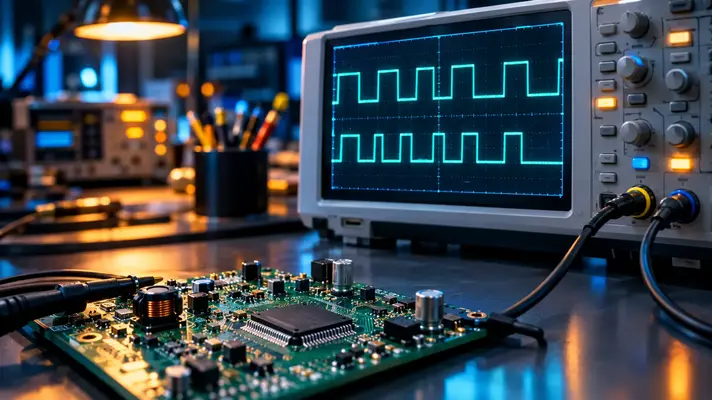
DPWM stands for Digital Pulse Width Modulation. It’s a method of controlling power by switching a signal on and off very fast, using a digital circuit to set how long each “on” pulse lasts.
In most technical contexts, the DPWM full form is exactly this. Some organizations use the same letters for other things, such as public works departments. If you found the term near words like “converter,” “duty cycle,” or “controller,” you’re in the right place.
The Core Idea in Plain English
Imagine flicking a light switch on and off a thousand times per second. If the light stays on 30% of each cycle, your eye sees a dim bulb. Stay on 80% of the time, and it looks bright.
That percentage is called the duty cycle. DPWM is simply a digital way to pick that percentage and repeat it with precision.
How Does DPWM Actually Work?
A DPWM module lives inside a microcontroller, FPGA, or dedicated power-management chip. It receives a number from a control algorithm, such as “give me 42.5% duty,” and turns that number into a real switching waveform.
The usual recipe has three parts:
- A counter that ticks upward with every clock pulse
- A comparator that checks the counter against the target number
- An output stage that flips high or low based on that comparison
When the counter starts a new cycle, the output goes high. Once the counter passes the target value, the output drops low. The wider the gap, the longer the pulse.
A Quick Worked Example
Say your chip runs a 100 MHz clock and you want a 1 MHz switching frequency. The counter has 100 steps per cycle. Each step is 10 nanoseconds, so your duty cycle can only move in 1% jumps.
That’s the heart of DPWM design. The clock limits how finely you can tune the pulse, and that limit has a name.
DPWM Resolution: The Number That Matters Most
Resolution is the smallest change in duty cycle a DPWM can make. It’s usually expressed in bits. The formula is simple: bits = log₂(clock frequency ÷ switching frequency).
In our example, 100 steps equals roughly 6.6 bits. That’s coarse for a precision power supply. A converter that needs to hold its output within a fraction of a percent will struggle.
Why Low Resolution Causes Trouble
When the DPWM can’t hit the exact duty cycle the controller wants, the output hunts back and forth between two nearby values. Engineers call this limit cycling. You see it as a tiny, persistent ripple in the output voltage.
A good rule of thumb is that DPWM resolution should be finer than the resolution of the analog-to-digital converter (ADC) measuring the output. Otherwise, the controller keeps chasing a target it can’t reach.
Common DPWM Architectures
Engineers have several ways to squeeze more resolution out of a limited clock. Each one trades size, power, and complexity.
Counter-Comparator DPWM
This is the simplest design and the one described above. It’s cheap and reliable, but resolution depends entirely on how fast you can clock it. Going from 8 to 12 bits means a clock 16 times faster.
Delay-Line DPWM
This design passes the signal through a chain of tiny delay cells and picks the tap that matches the target. It reaches very fine timing without a huge clock. The downside is that temperature and manufacturing variation change the delays.
Hybrid DPWM
Most commercial chips use this approach. A counter handles the coarse timing, and a delay line handles the fine timing. You get high resolution without an impractically fast clock.
Dithering
Here the controller rapidly alternates between two neighboring duty values so that the average lands in between. It’s a clever software trick that adds effective bits at almost no hardware cost.
DPWM vs Analog PWM
Both create pulse-width signals. They just get there differently. Here’s how they compare:
| Feature | Digital PWM (DPWM) | Analog PWM |
| Signal source | Counter and comparator logic | Ramp generator and analog comparator |
| Tuning | Change a register value in software | Swap resistors or capacitors |
| Drift with temperature | Very low | Noticeable |
| Flexibility | High, reprogrammable on the fly | Limited once built |
| Resolution limit | Set by clock speed | Set by noise and component quality |
| Best for | Smart, adaptive power systems | Simple, low-cost, ultra-fast designs |
Digital wins on flexibility and repeatability. Analog still holds an edge in raw speed and simplicity, which is why cheap power supplies often stick with it.
Where You’ll Find DPWM in the Real World
The DPWM meaning becomes real when you look at the devices around you. Anywhere power needs to be shaped, sliced, or smoothed, it’s likely at work.
- DC-DC converters: Laptop chargers, phone chargers, and server power supplies use it to hold voltage steady
- Motor drives: Electric vehicles, drones, and washing machines rely on it for smooth speed control
- LED lighting: It dims lamps without color shift or visible flicker
- Class-D audio amplifiers: It turns a sound signal into pulses that drive speakers efficiently
- Solar inverters: It shapes DC power into clean AC for the grid
A Practical Insight
Digital control lets a supply adapt. A DPWM-based converter can change its behavior when the load jumps, the battery ages, or the temperature climbs. Analog designs need a hardware redesign to do the same.
That adaptability is a big reason digital power management took over data centers and electric vehicles.
Advantages and Limitations of DPWM
No technology is perfect. Here’s an honest look at the trade-offs.
Advantages
- Programmable: Update the behavior with firmware instead of a soldering iron
- Stable: Digital values don’t drift when the temperature changes
- Integrable: It fits neatly beside other digital logic on one chip
- Smart features: Soft-start, fault protection, and telemetry come almost free
Limitations
- Resolution ceiling: Fast switching frequencies eat up clock cycles quickly
- Delay: Sampling and computation add a small lag in the control loop
- Power draw: Very fast clocks burn energy, which matters in tiny battery devices
How to Choose the Right DPWM Setup
If you’re picking a controller or designing your own, start with your switching frequency. Then work backward to find the clock speed you need for your target resolution.
Aim for at least 10 to 12 effective bits in precision converters. For simple LED dimming or a hobby motor, 8 bits is often plenty. Don’t overbuild what your application doesn’t demand.
If a chip’s datasheet advertises “high-resolution DPWM,” check whether it uses a hybrid or dithering technique. That tells you how it reaches those extra bits.
Final Verdict
Now that the DPWM meaning is clear, you can see why this small acronym is the quiet engine behind efficient modern power. Understand its resolution, pick the right architecture, and you can avoid the ripple and instability that trip up many first designs.
Here’s the insider tip: when a converter misbehaves, check DPWM resolution before you blame the control algorithm. Many “mystery” oscillations turn out to be a duty cycle that simply couldn’t land where the controller aimed.